Release Date:2024/09/03
What is Cold Forging Simulation with CAE? – Benefits & Case Studies
By designing, verifying, and modifying processes with CAE (Computer-Aided Engineering) on a computer, it is possible to reduce the time and resources required for manufacturing prototypes and trials. This approach significantly shortens lead times for product development.
In this article, we will focus on Cold Forging and provide an overview of the process, discuss the advantages of CAE analysis, and share examples of analysis applications.
Contents
What is Cold Forging?
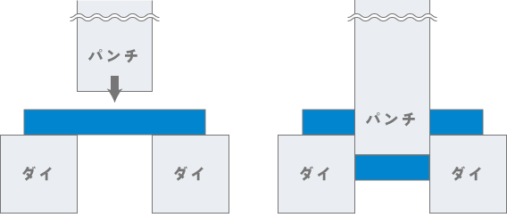
Cold forging is a metal forming method that uses high working pressure and high-precision dies at room temperature. Since the process is less affected by temperature, the accuracy of the die is directly transferred to the final product shape (net shape) or a shape close to it (near-net shape). Through proper process design, heat treatment, and lubrication between stages, cold forging can achieve highly accurate results.
Recently, advancements in manufacturing methods have enabled the integration of multiple movable dies into press machines, further shortening the forming process.
However, cold forging has certain limitations. Due to the high deformation resistance of metals at room temperature, this method is not suitable for forming complex shapes. Additionally, the high processing pressure required makes it unsuitable for forming large products.
Benefits of CAE Analysis for Cold Forging
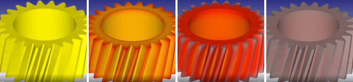
CAE (Computer-Aided Engineering) analysis for cold forging offers several advantages. It enables the visualization of load and deformation transitions in the material during the forming process, as well as the prediction of potential defects, such as cracks, that may occur during forming. This allows for the verification of feasible shapes and whether they can be formed within the specifications of the forging machine, all before trial production. As a result, costs associated with trial-related dies and labor can be significantly reduced.
Additionally, CAE analysis allows for the evaluation of the load (stress) applied to the dies, which can be used to improve die life. This contributes to reducing overall forging production costs.
Example of Cold Forging Simulation with CAE Solution
Here are some examples of simulations using the CAE software DEFORM.
※What is the CAE software “DEFORM”?
DEFORM is the comprehensive machining simulation software for all types of metal processes, including forging, machining, and heat treatment.
With a wide variety of analysis functions, our customers come from various fields, including the automotive, steel, aerospace, electrical/electronics, and chemical industries.
For more detailed information, please click the link below.
The CAE software “DEFORM” is your best partner in plastic forming
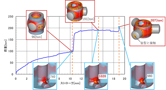
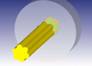
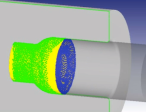
Case Study: Simulation of Component for Constant Velocity Joints
The figure below illustrates the load transition and deformation transition during the forming process. It reveals that the deformation significantly changes at the timing of load variations.
While the forming load reaches its peak at the end of the forming process, the load on the die is highest during the middle of the process. These insights, which can be newly discovered through CAE simulations, provide valuable information for optimizing the forming process.

Other Case Studies (Click on the image to visit the 3D animation page)


Thank You for Reading
We hope you found this article informative and insightful.
By leveraging CAE, it is possible to prevent defects in advance, while also reducing costs and shortening lead times. The CAE software DEFORM offers a wide range of features to support designers, including capabilities for additional processes, data analysis, experimental design modules, and optimization modules.
If you have any questions or concerns regarding product design or manufacturing, please do not hesitate to contact us.